PV198 Study Materials
Preliminaries
Theory
- Introduction
- GPIO
- Interrupts
- Timer
- PWM
- ADC
- Communication buses
- SPI
- I2C
- UART
Practical
ADC
- Foreword
- Reasons for ADC/DAC use
- Basic ADC operation
- Basic ADC properties
- Modes of operation
- Basic ADC types
Foreword
Although computers use digital signals (just ones and zeroes), we still have the need to work with analog signals (continuous value, theoritecally infinite precision).
The reason is that many sensors still output an analog signal and the majority of our world is analog by nature.
To convert signals from analog to digital we use Analog-Digital Converters (ADC for short).
The other direction is done with Digital-Analog converters (DAC), which we will not cover here.
This chapter will serve as a very quick overview of ADCs.
They are quite complex devices and we only require a very basic understanding of them.
Reasons for ADC/DAC use
There are two main reasons for using an ADC:
- Many
sensorsstill output analog value (temperature sensors, light intensity sensors…) - Many
common signalsare still analog (audio signals, radio signals)
Thus, when we want to work with a value from some sensor, or for example work with audio, we need to convert the signals to their digital representation. Similarly, when we want to output for example an audio signal, we will need to use a DAC to do so.
Basic ADC operation
The basic operation cycle of ADCs is quite simple and can be summarized in a few steps:
- Sample and hold the input value
- Convert the held value to a digital one
- Output the digital value
- Clear the held value
- Repeat
The most critical step is the second one and is also the one by which ADCs are categorized (more on that later).
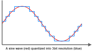
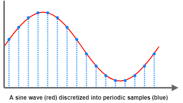
The first two steps are also called discretization and quantization.
We first select discrete time instants at which we sample and hold the continuous analog input value.
After this step, we still have a continuous value, which is converted into discrete value steps in the second step.
This is the so-called quantization - we map the continuous value into a set of discrete values.
Basic ADC properties
ADCs have many properties we can care about, but for this course, we will only look at two major ones: resolution and sampling rate.
Resolution
Resolution is the amount of separate digital values the ADC can output.
It’s usually given in bits.
A 2bit ADC can output 00, 01, 10, 11 as the values, 4 in total.
The ADC has to round the continuous analog signal into discrete values, so there always be some error caused by this.
Most ADCs required a signal named Vref (reference voltage), which represents the voltage that should be converted into maximum value (all ones).
The resolution is the size of the set of discrete values we map during the quantization step (second step).

Sampling rate
The sampling rate is how often the ADC can do the conversion.
The usual unit here is Hz (Hertz), but you can also encounter sps (Samples per second).
An ADC with 1kHz sampling rate will do 1 thousand conversions every second.
This speed is only the maximum the ADC can do, you can easily run a 1kHz ADC at only 100Hz.

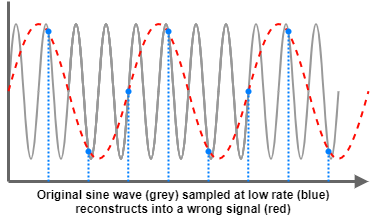
There is an important theorem related to sampling rate: Nyquist - Shannon sampling theorem.
It states that to reconstruct a continuous signal of frequency f, we need to sample it at atleast twice the frequency -2*f.
Usually, to get any meaningful data from the conversion, we actually need a lot higher sampling rate.
The usual rule of thumb is ten times higher than the signal.
A quite nice interactive example can be found here.

Modes of operation
There are two common modes of operation for conversion in ADCs:
Single Shot- the ADC does a single conversion when instructed and stopsContinuous- the ADC does conversions at a set speed (sampling rate)
We can also briefly look at the two most common input modes for ADCs:
Single Ended- only single input is needed for one signal, measured against ground andVrefDifferential- requires two inputs for one signal, measures the voltage difference between the two inputs (with the maximum difference beingVref)
Basic ADC types
There are 4 major categories of ADCs:
Flash ADCs- These do the conversion step in a single cycle and can achieve very high sampling rates.
- Very expensive and hard to use.
Pipeline ADCs- Divide the single conversion cycle of flash ADCs into multiple cycles in a “pipeline”.
- Balance speed and price.
Successive Approximation (SAR) ADCs- Approximate the value bit by bit, starting at the most significant bit.
- Very cheap, used in most microcontrollers, and slow.
Sigma-Delta ADCs- Use a fairly complicated oversampling and decimation algorithm.
- Very precise, high-resolution output, but slow.