PV198 Study Materials
Preliminaries
Theory
- Introduction
- GPIO
- Interrupts
- Timer
- PWM
- ADC
- Communication buses
- SPI
- I2C
- UART
Practical
Timer
This chapter will focus on one of the most common peripherals, the timer.
As can be infered from the name, it is mostly used for any kind of timing purposes, of both input or output events.
This chapter will be a quick overview of how do timers generally work and few main modes of operation.
Let’s first look at the underlying part of the timer, called a counter.
Timer is nowadays synonymous with counter and the terms are often used interchangeably.
Counter
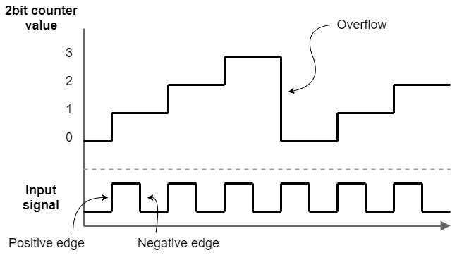
Counter is a simple logical circuit that can count how many events happened (for example pulses).
The value is stored in a register.
The size of the register gives us limit on the stored value - 8bit counter will count up to 255.
When the counter counts up from the maximum value, it overflows back to zero.
This is often used mechanic of the counter, most commonly to cause an overflow interrupt to go off.
The counter’s input is a logical signal.
Most counters will count up on a positive edge, ie on change from logical 0 to logical 1.
They can also commonly be set to count on negative edge, from logical 1 to logical 0.
Counters can often be bidirectional - they can also count down. Then they can also underflow back to maximum value.

Counters are used in many applications, from counting button presses or other impulses to edge counting and timing.
Timing and clocks
When timing anything in digital logic, we need a stable timing signal which we can reference and use it to derive time steps.
This signal is called a clock.
Most common form of a clock is a periodic on/off digital signal of known frequency.
For example, a 1MHz clock can be used to derive timesteps as small as 1/1000000 of a second, that is 1 microsecond.
The input signal on the previous image is also an example of a clock signal.
Modern MCUs have very complex clocking schemes, where each peripheral, the core and the registers all can receive different clocks with different frequencies.
When we feed a clock signal into a counter, we create a timer.
Timers are the most common use case of counters, so common that you will only encounter timer peripherals.
Most timer peripherals can still be used as a normal counter, but there are some exceptions.
If we have a timer that is clocked at 1KHz and the internal counter has value of 1000, we know that 1s has passed.
Counter/Timer compare output
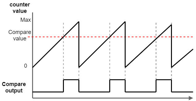
Apart from using the counting register as an output value of the peripheral, we also often use something called compare output.
We can compare the value register against a configurable compare value and use the result as an output.
It can either be used to set off an interrupt or it can be used as logical output.
This output is commonly used to generate external signal.
More details about this use case are in their separate PWM chapter.

PIT Timer
Periodic Interrupt Timer is a peripheral specific to the MCU family we use on our devkits.
As can be deduced from the name, it will generate periodic interrupts.
We can configure how often the interrupts happen.
The peripheral has 4 semi-independent timers (also called channels) we can use. They are a countdown timers which generate an interrupt when they reach zero. When the interrupt happens, the internal counter is reset back to a configured value. By configuring this value, we can change the frequency of the interrupt.
The channels share the input clock signal, but the reset value is configurable for each separately. This way we can have separate interrupt frequencies which are still synchronized.
When we need a longer period between interrupts than what can be achieved with a single channel, we can chain them together. When a first channel underflows, rather than generating an interrupt, it will cause the chained channel to count down by one. Only when the second chained channel reaches zero, the interrupt will be generated.