PV198 Study Materials
Preliminaries
Theory
- Introduction
- GPIO
- Interrupts
- Timer
- PWM
- ADC
- Communication buses
- SPI
- I2C
- UART
Practical
SPI
SPI - Serial Peripheral Interface is simple to implement (in the hardware) and it is simple to use.
It is used to communicate with simple or even complex devices.
As it is relatively cheap to implement this interface within the hardware, it can be found frequently in external devices.
Properties
SPI is a bus, full-duplex, synchronous, and works in a master/slave mode.
That means that we can share the communication wires between multiple devices, there is one master device that controls the communication and multiple slaves.
We have wires for both directions of communication and we also have a wire with a synchronization clock.
The communication normally happens only between the master and the currently active slave device.
The master controls which device is active.
Wires
There are three core signal wires for SPI:
CLK: Signal wire with the clock is used to synchronize the communication. (wire is controlled by themaster)MISO:MasterInSlaveOut wire - the flow of data is from theslaveto themaster(the wire is controlled by theslave).MOSI:MasterOutSlaveIn wire - the flow of data is from themasterto theslave(the wire is controlled by themaster).
All of these signals are shared between all devices, for example: MISO is a wire that goes from the master to each slave - all slaves are connected to the same wire.
There is one more signal between master and each slave - CS (chip select).
This is signal is unique for each slave and is controlled by the master.
That implies that if we have 4 slaves, there has to be 4 CS wires connected to the master.
Typically, if the signal is LOW, that slave is selected, if the signal is HIGH, that slave is not selected.
Data lines signals which are not necessary can be omitted.
We can even communicate with multiple slaves at once if the MISO line would not be used by them.
Data exchange
Data exchange is initiated by the master. Both devices always exchange the same amount of data.
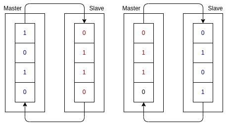
Usual representation of this process is with two shift-registers:

Both devices contain inner shift-register to which data for the other devices is prepared. Once the communication starts, the shift-registers are just rotated.
And at the end of the process, the registers contain data from the other device.
Both devices load data from those registers as input.
The amount of data and their semantics depends on the context.
Topology
SPI is simple and not binding. This gives us opportunity for different physical topology. In this course we will mention the most common configuration, and also one creative alternative (daisy-chain).
Basic configuration

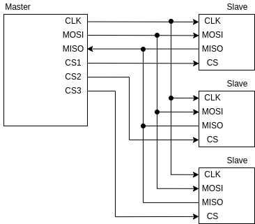
The basic configuration connects slaves in a way, that MISO, MOSI, and CLK are shared among all the devices.
CS lines exists for each slave independently and are connected just between the master and appropiate slave.
Master can properly select wanted slave and communicate with it independently. Downside is that we need one line for each slave.
Daisy-chain

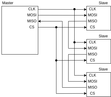
This configuration connects all the devices in circle.
Data from one device are sent to the next device in the circle.
(slaves form a chain in the circle)
With this, we can drive multiple slaves using only one CS signal.
Downside is that we can not access only single slave device without writing through another slave device.
This topology takes advantage of the fact that some devices only serve as shift registers and react to only latest 8 bits transfered to them and send forward all other overflowing data. That is, only some devices are compatible with this.
Edits
- 12.12.2022 - Fixed wrong wiring in pictures