PV198 Study Materials
Preliminaries
Theory
- Introduction
- GPIO
- Interrupts
- Timer
- PWM
- ADC
- Communication buses
- SPI
- I2C
- UART
Practical
Introduction
Core
We are working with microcontrollers (MCU) - small chips that integrate processor, RAM memory (runtime memory) and FLASH memory (storage memory). Commonly we assume the following properties:
- small size
- small power usage
- limited resources
- low frequency (around the range of
16MHz..800MHz) 32bitor lower architecture (8bitcontrollers are still used)- small RAM (around the range of
16KB..256KB) - small FLASH (around the range of
32KB..2MB)
- low frequency (around the range of
- limited instructions (
floating point unit (FPU)is not common everywhere) - limited debugging experience
printingdebug information may disturb the system- traditional debugging is functional, but not usable for bugs based on interaction with the environment
- lack of
general purpose operating system (GPOS)- that implies a lack of facilities for a
filesystem,stdout/stdin,GUI, etc… - we use
RTOSinstead - much simpler and lightweight operating systems designed for MCUs
- that implies a lack of facilities for a
- easier real-time control
MCUis commonly simpler and has more deterministic behavior - better for real-time control
The end goal of the course is to educate you about how to develop these systems in general. That is not possible due to practical reasons, instead, we will teach you the basics of one specific system in a way, that optimizes for transferability to other contexts.
The course uses an MCU with ARM architecture, with more resources than an average chip, and one that has in our opinion one of the better tools.
To be able to work on that chip, we will use a development kit - a special board sold by the manufacturer that is designed for prototyping.
Peripherals
In traditional systems, we commonly imagine that the system is composed of a core (computing unit with registers), RAM (runtime memory) and storage (long-term memory).
That mental model is not enough for embedded.
In embedded, the basic components are Core, RAM, Flash (long-term storage), and peripherals.
Each peripheral is a part of the MCU (it’s present in the chip) that implements certain functionality that can be used by the MCU.
For example, the GPIO peripheral takes care of work with the physical pins of the MCU.
The peripherals are directly accessible by the Core unit and have a tight relationship.
There exist multiple types of peripherals, but how exactly they function depends heavily between manufacturers and generations of MCUs.
Given that manufacturers tend to share the design of the peripheral between specific MCUs, peripherals in one generation of one manufacturer may behave similarly.
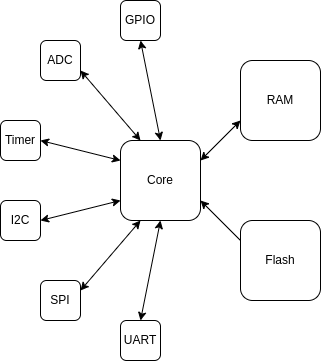
Common peripherals are:
GPIO- handles digital pins of theMCUADC- handles input analog pins - measuring voltageDAC- handles output analog pins - producing specific voltageTimer- able to measure time, generate periodic events, count external inputsI2C- implements communication overI2CorSMBusSPI- implements communication overSPIUART- implements communication overUARTorRS-485USB- implements communication overUSB(usually as a slave)DMA- handles DMA transfers in the chip
Interfacing peripherals
The exact way of interfacing the peripherals is implementation-defined, for the sake of this course we will explain a way used in our context. To do that, let’s explain some preliminary knowledge.
The MCU we are using is 32bit, which means up to 4GB of RAM, which is much more than could appear on embedded devices - memory will not use up the address space and we can designate parts of it to different use cases.
Each peripheral under consideration specifies registers that are used for interfacing with it, these registers contain data and setting/reading said data may cause real-life effects. For example:
- direct control of
GPIOpins - if bitiin registerXhas value1, then the pinjofMCUwill have logical1on its output. - bits that start/stop some process with the peripheral (operation
start timer Xis done by setting bitito1in registerAoftimer X) - reading data - value read by
ADCperipheral is stored in registersX(top 8 bits) andY(lower 8 bits)
Each register of each peripheral has an assigned address in the address space of the device.
Usually, the manufacturer specifies something like this: addresses with prefix 0x1 are reserved for addresses in RAM and addresses with prefix 0x4 are reserved for registers of peripherals.
The generated code uses the same assembly instructions to interface with the registers as for other parts of the memory.
(With some exceptions, for example, PIC processors have special instructions for registers)
You will not interface with this directly.
Instead, we will focus on a high-level API in form of C functions provided by the manufacturer, these just do read/writes into registers internally.
Flashing, debugging
Let’s describe the build process first:
- Compiler (fork of
GCCis commonly used) compiles the code (made ofCUs (compilation unit)) and startup script. CUs are linked together with a startup script to form a binary.- The binary is a full standalone binary image - new content of the flash memory of the
MCU. - The startup script controls the startup process of
MCU- beforemain()is executed.
- The binary is a full standalone binary image - new content of the flash memory of the
This works similarly to on a GPOS-based system, with the exception that we use a slightly different compiler and the output is different - standalone binary instead of executable.
To flash or debug the MCU, we need a special device to interact with the MCU - programmer.
It’s a special device that is connected to the host computer and the MCU and gives the host computer ability to flash or debug the device.
Programmers are standardized, in the sense that they use commonly available protocols to communicate with the MCU (JTAG is most common, on ARM we can also use SWD).
That means that some more generic programmer should work for any MCU, but in reality, you always have to check for compatibility - however, we do have some degree of it.
If you want to have the best experience (fastest flashing, most capable debugging), it can be better to acquire a specific programmer for that MCU. On the side of the computer, we also need software support to interact with the programmer, either a tool provided by the manufacturer or generic tools (For example, OpenOCD).
In this course we do not have to worry about this, as the programmer is integrated into the development board we are using - we just need a USB cable to connect the device to computers. On the software side, we will be using IDE from the manufacturer, which has a fully integrated build system, compiler, flashing software, and debugging capability. This way you do not have to worry about this.